
This is a follow-up to my previous post on emergent ecosystem engineering in epikarst, so I won't repeat much of the background or analytical details. There I argued that interactions among rock weathering, moisture flux, biological effects (particularly roots and their symbionts) and soil operate such that if weathering is moisture-limited, and biota are limited by water availability and below-ground space, the system is dynamically unstable. Positive feedbacks dominate so as to reinforce or accelerate dissolution, joint/fracture widening, root growth, and soil accumulation. The net effect is to develop the epikarst as increasingly hospitable habitat. This continues, according to the analysis, until weathering becomes reaction-limited and subsurface space and moisture are no longer significant limiting factors for plant growth. Under the latter circumstances the system is dynamically stable, implying resilience to relatively small changes or disturbances and slower change.
But what about non-carbonate parent rocks? There are some key differences. In epikarst, ground water flow is dominated by fissures and conduits. In non-karst, matrix and macropore flow may be more important, and chemical weathering may facilitate moisture penetration independently of widening of joints and fractures. Also, though this is a bit oversimplified, dissolution of carbonates results in removal of material in solution and the creation or widening of fissures and cavities. In other rocks, chemical weathering is often more selective, removing or modifying more soluble and less resistant minerals first, and increasingly concentrating more resistant ones. Thus the rate of weathering slows down as weatherable minerals are depleted--a self-limitation effect independent of moisture penetration. Also, because conduits are less common (and smaller), plugging or flushing of sediments therein is rarely an issue.
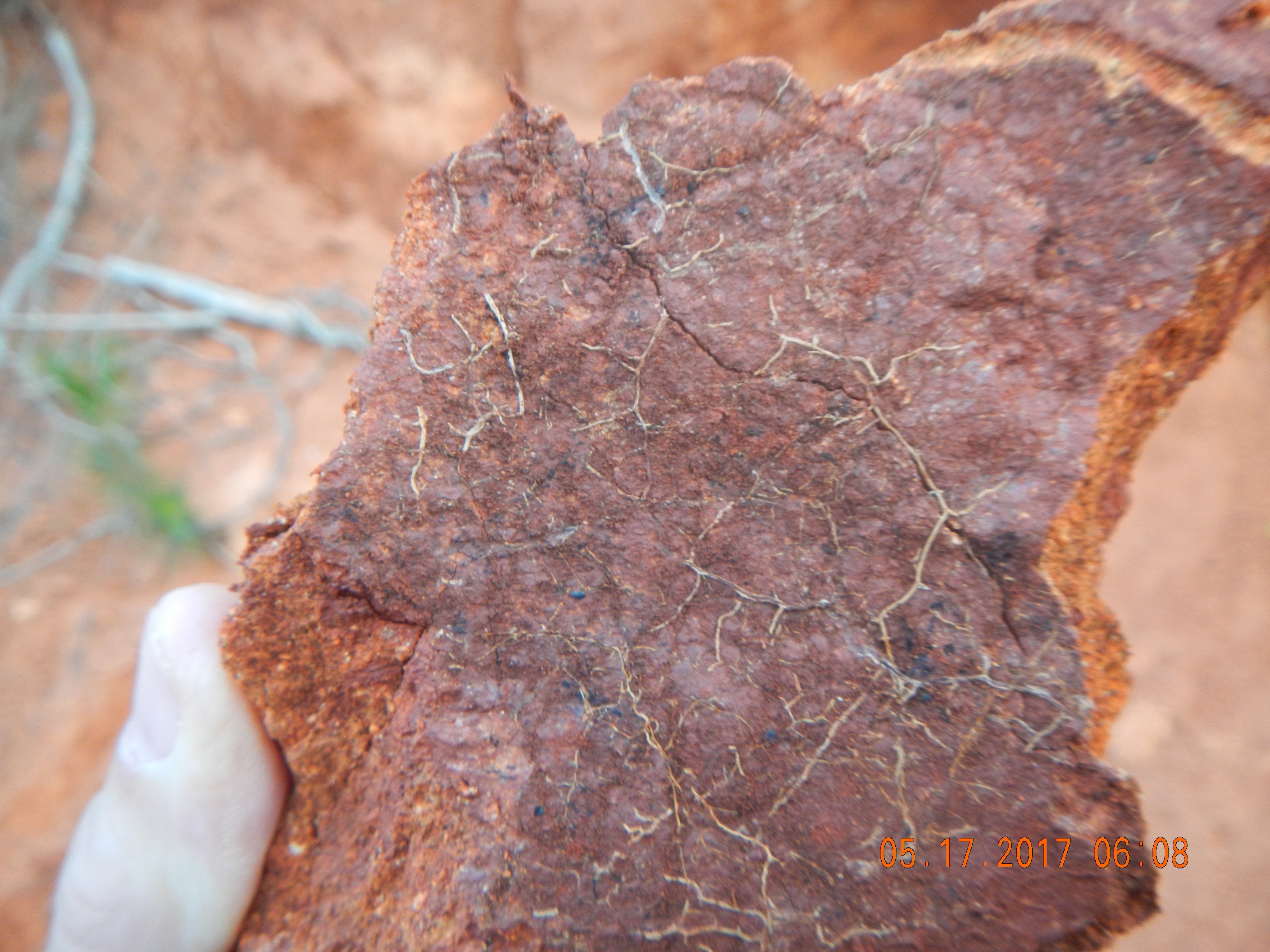
Granitic saprolite from upland South Carolina with fine roots in a weathered parting >2 m below the surface.
Figure 1 below is a similar system model to that of the epikarst post, to which you can refer for a more complete explanation of the links. To cut to the chase, applying the same type of analysis to the non-epikarst model produces the same general result.
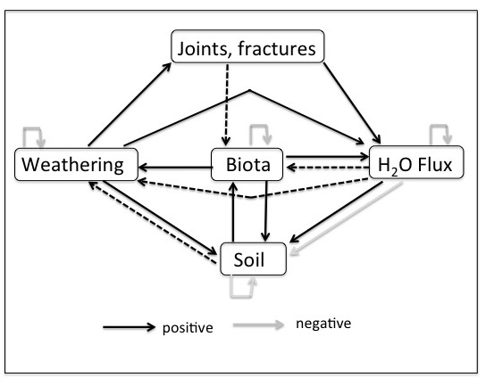
Figure 1. Interaction system. Dotted lines indicate links that are positive when present, but that may become inapplicable as regolith develops.
When self-limitations (depletion of weatherable minerals, biological saturation, external moisture supply) are not approached, biological production is stimulated by additional space and subsurface moisture, and chemical weathering is moisture-limited, the system is dynamically unstable. Positive feedbacks dominate, and absent disturbances that radically change any component, weathering, soil, biota, and moisture flux are all mutually reinforcing. As this creates ever more suitable habitat, this can be viewed as ecosystem engineering (EE). Dynamical stability obtains when self-limitations are approached, biota are not generally limited by water or belowground space, and chemical weathering is reaction rather than moisture limited most of the time.
As with the epikarst case, though the processes by which EE occurs may continue, they no longer operate so as to create more favorable habitat for the surface organisms (woody plants) primarily responsible. Thus in both cases, the EE is emergent in that it derives from interactions that occur in certain exposed rock or thin-soil settings and is not directly associated with traits of the engineer organisms. And in both epikarst and non-carbonate settings, the EE is self-limiting as factors other than water and subsurface space become constraining.
Table 1. Interaction matrix for the system shown in Figure 1.
|
|
Joints, fractures1 |
Weathering |
Biota |
Water flux |
Soil |
|
JF |
0 |
0 |
a13 |
a14 |
0 |
|
W |
a21 |
-a22 |
0 |
a24 |
a25 |
|
B |
0 |
a32 |
-a33 |
a34 |
a35 |
|
WF |
0 |
a42 |
a43 |
-a44 |
+a45 |
|
S |
0 |
a52 |
a53 |
0 |
-a55 |
Table 2. Feedbacks for the system shown in Figure 1 and Table 1. One of the criteria for dynamical stability is that all FN < 0.
|
FN = feedback at level N |
|
F1 = (-a22) + (-a33) + (-a44) + (-a55) |
|
F2 = a24a42 + a43a34 + a52 a25 + a53a35 + - (-a33)(-a44) - (-a33)(-a55) - (-a44)(-a55) . . . |
|
F3 = a13a32a21 + a14a42a21 + a24a43a32 + a24(+a45)a52 a25a53a32 + a35(-a54)a42 +a45a53a34 - a43a34(-a22) - a53a35(-a22) + (-a33)(-a44)(-a55) |
|
F4 = a21a14a43a32 + a24a43a35a52 + a52a21a14(+a45) + a35a52a21a13 + (-a54)a43a32a25 - a13a32a21(-a44) - a25a53a32(-a44) - a13a32a21(-a55) - a14a42a21(-a33) - a14a42a21(-a55) - (a43 a34)(a52 a25) - a13a32a21(-a44) - a13a32a21(-a55) |
|
F5 = a52a21a13a34(+a45) + a53a32a21a14(+a45) - a21a14a43a32(-a55) - + a52a21a14(+a45)(-a33) - a35a52a21a13(-a44) - (a14a42a21)(a53a35) + (a13a32a21)(-a44)(-a55) + a14a42a21(-a33)(-a55) |
(Posted 23 September 2017)